The BMI160 is a small, low power, low noise 16-bit inertial measurement unit designed for use in mobile applications like augmented reality or indoor navigation which require highly accurate, real-time sensor data.
In full operation mode, with both the accelerometer and gyroscope enabled, the current consumption is typically 950 μA, enabling always-on applications in battery driven devices
Features
| Parameter | Technical data |
|---|---|
| Digital resolution | Accelerometer (A): 16 bit Gyroscope (G): 16bit |
| Measurement ranges (programmable) |
(A): ± 2 g, ± 4 g, ± 8 g, ± 16 g (G): ± 125°/s, ± 250°/s, ± 500°/s, ± 1000°/s, ± 2000°/s |
| Sensitivity (calibrated) | (A): ±2g: 16384LSB/g ±4g: 8192LSB/g ±8g: 4096LSB/g ±16g: 2048LSB/g (G): ±125°/s: 262.4 LSB/°/s ±250°/s: 131.2 LSB/°/s ±500°/s: 65.6 LSB/°/s ±1000°/s: 32.8 LSB/°/s ±2000°/s: 16.4 LSB/°/s |
| Zero-g offset (typ., over life-time) | (A): ±40mg (G): ± 10°/s |
| Noise density (typ.) | (A): 180 μg/√Hz (G): 0.008 °/s/√Hz |
| Bandwidths (programmable) | 1600 Hz … 25/32 Hz |
| Digital inputs/outputs | SPI, I²C, 4x digital interrupts |
| Supply voltage (VDD) | 1.71 … 3.6 V |
| I/0 supply voltage (VDDIO) | 1.2 … 3.6 V |
| Temperature range | -40 … +85°C |
| Current consumption – full operation – low-power mode |
950 μA 3 μA |
| FIFO data buffer | 1024 byte |
| LGA package | 2.5 × 3.0 × 0.8 mm³ |
| Shock resistance | 10,000 g x 200 μs |
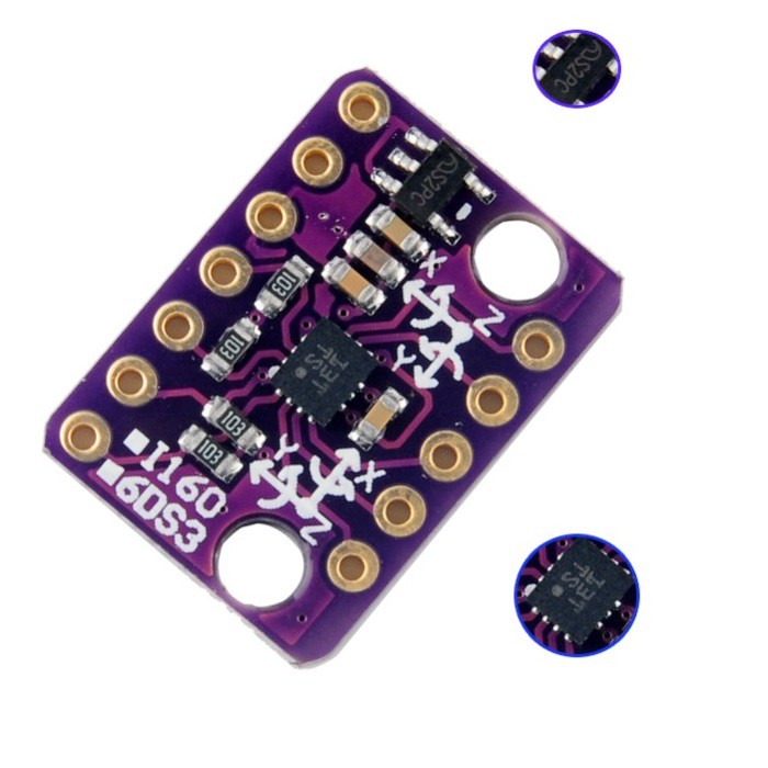
Typically you would buy a little module which makes it easier to connect up to an arduino, this is the module that was purchased. It does look a little confusing as you can see its marked with 2 different names on the silkscreen and more often than not there is no check in the box called I160 . Just something to look out for.

bmi160 module
Connection
Being an I2C device its easy to connect to an Arduino, watch out though you need to power this off 3.3v, some modules may have a step down regulator but this cannot be guaranteed
| Arduino Uno pin | Module Pin |
| 3v3 | 3v3 |
| Gnd | Gnd |
| SDA – A4 | SDA |
| SCL – A5 | SCL |
You can also connect the device in SPI mode
Code
This example used the following library which makes life easier – https://github.com/hanyazou/BMI160-Arduino
You can connect the sensor in I2C or SPI modes, you need to change the wiring and the initiliaze device in the code
[codesyntax lang=”cpp”]
#include <BMI160Gen.h>

const int select_pin = 10;
const int i2c_addr = 0x69;

void setup() {
  Serial.begin(9600); // initialize Serial communication
  while (!Serial);    // wait for the serial port to open

  // initialize device
  //BMI160.begin(BMI160GenClass::SPI_MODE, select_pin);
  BMI160.begin(BMI160GenClass::I2C_MODE, i2c_addr);
}

void loop() {
  int gx, gy, gz;         // raw gyro values

  // read raw gyro measurements from device
  BMI160.readGyro(gx, gy, gz);

  // display tab-separated gyro x/y/z values
  Serial.print("g:\t");
  Serial.print(gx);
  Serial.print("\t");
  Serial.print(gy);
  Serial.print("\t");
  Serial.print(gz);
  Serial.println();

  delay(500);
}
[/codesyntax]
Output
Open the serial monitor and you should readings like the following, move the sensor about to see different values
g: 90 86 9
g: 69 69 40
g: 35 97 -9
g: -7370 3961 -1786
g: -31829 -2652 32767
g: -3221 25109 32767
g: 26020 31878 -26125
g: -20332 -21698 -15712
g: -7297 3463 -1723
g: -1137 1521 420
g: -203 305 96
g: 144 -102 54
g: 77 116 35
Links
https://ae-bst.resource.bosch.com/media/_tech/media/datasheets/BST-BMI160-DS000-07.pdf
CJMCU-160I BMI160 latest inertial measurement sensor attitude module 6DOF
