A reed switch is a small device that when the device is exposed to a magnetic field, the two materials inside the switch pull together and the switch closes. When the magnetic field is removed, the two materials then separate and the switch will open.
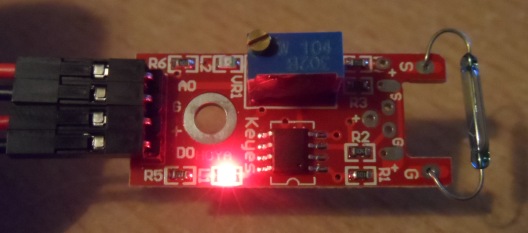
Here is a picture of the reed switch module we will be using in this example, it comes from a 37 piece module kit, link at the bottom.

reed switch
Here is the pinout of the reed switch module in detail
| Pin | Label | Arduino Connection | |||
| 1 | AO | Analog input | |||
| 2 | G | Ground (GND) | |||
| 3 | + | 5 volt power | |||
| 4 | DO | Digital input |
We will connect the module, read the analog and digital signals and monitor using the serial monitor, we will then postion the reed switch near a magnetic source and see if the readings change.
Code
[codesyntax lang=”cpp”]
// Arduino pin numbers
//D2 and A0 used
const int digital = 2;
const int analog = 0;

void setup()
{
pinMode(digital, INPUT);
Serial.begin(115200);
}

void loop()
{
Serial.print(digitalRead(digital));
Serial.print("-");
Serial.println(analogRead(analog));
delay(250);
}
[/codesyntax]
Result
Here are the results you will see
As you can see there are two basic sets of values
1/ The reed switch open/ no magnet – 0 and 1023
2/ The reed switch closed/ magnet present – 1 and 0
Links
Here are links to the sensor kit
Ultimate 37 in 1 Sensor Modules Kit for Arduino from Amazon UK
Ultimate 37 in 1 Sensor Modules Kit for Arduino from Amazon US
